EMC protection of USB applications
Concerns regarding the susceptibility of USB ports are even raised in Intel’s "High Speed USB Platform Design Guidelines". Intel recommends the use of current-compensated chokes for EMI suppression and further components for protection against electrostatic discharge. Electronics are exposed to electrostatic discharge. ESD pulses have voltages of up to 30 kV and and are therefore hazardous for all types of integrated circuits. Some current ICs are "safe" against ESD, but this safety is only guaranteed for a small selection of the potential threats. Daily practice shows: Additional protection is indispensable. Only with external protection is the complete board ESD-free and highly dependable products can be developed. Dedicated suppression measures are equally imperative. Wireless connected electronic devices are to be found in all spheres of life and their number is growing continuously.
It is important to make one’s own products immune to interference radiation. Only if the anticipated forms of interference are considered, can the necessary suppression components be immediately integrated in the design and development time reduced. As we know, the radiated interference of one’s own product also has to stay below a certain level. This is very precisely evaluated by EMC test laboratories. If the product fails this test, the costs for reworking very soon exceed the costs of suppression components many times over.
Actually interference immune
Differential mode data transmission offers a significant advantage over the simple coaxial cable when it comes to the effect of interference on the USB. In the case of the inductive interference effect (magnetic field), the twisting of the wires achieves compensation of the interference effect. With symmetrization of the partial inductances of the respective twisted wire, the interference influences compensate each other. This interference immunity can be compromised in practice.
- The inputs/outputs of the USB controller are insufficiently symmetrical, the USB signal displays common mode interference.
- The layout is not HF/EMC compatible, parasitic capacitances and the lack of wave impedance matching generates common mode interference.
- The circuit design (USB filter) is inadequate, the filters affect the signal quality and/or the insertion loss is too low.
- The interface design (receptacle, housing) is inadequate. Poor ground reduces the shield attenuation of the cable. Filters have poor ground reference.
- The USB cable is asymmetrical, poorly shielded and has inadequate ground connection. The cable deteriorates the signal quality, radiates signal harmonics and has insufficient shield attenuation towards external interference sources.
The problem: Some of these points cannot be influenced, these include the technical realization of the purchased USB controller or the end user using "cheap" USB cables. So preventive measures have to be met to protect the interface from the effects of external interference, which can lead to the destruction of the USB controller and to limit interference radiation of signals via the cable.
Selection of the protection components
Protection against electrostatic discharge is defined as: protection against ESD pulses in accordance with EN 61000-4-2, protection against surge pulses according to EN 61000-4-5 as well as burst (EFT) pulses in according to EN 61000-4-4. Transient Voltage Suppressor (TVS) diodes have to fulfill these functions. Here it is important: To protect fast data lines like USB against overvoltage, TVS and ceramic ESD suppressors with low capacitance should be used, such that no distortion of the USB signal occurs. For this reason, Würth Elektronik eiSos develops components which are precisely optimized in this respect and are invisible on the data line. TVS diodes have capacitances below 1 pF and ceramic ESD suppressors with capacitances up to 0.2 pF are a good choice for protecting USB ports.
Several questions need to be asked when selecting the components: Is there a supply voltage for rail-to-rail connections (GND < I/O signal < Vcc)? Take a TVS diode. Is there no supply voltage or should ceramic components be preferred? In this case a TVS diode has to be chosen for which the VDD pin can float or ESD suppressors are used, such as the WE-VE "ULC" series from Würth Elektronik. Further questions: What maximum ESD voltage is expected? Should one or two USB ports be protected? Incidentally, if a USB data line is connected to two I/O pins of the TVS diode, this always produces better protection, which is why a TVS diode array should preferably be used.
Don’t forget the power supply
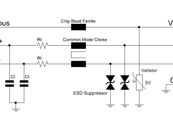
For an end-to-end EMC-compliant design, it is important to also filter the power supply (VBUS). Many developers neglect this point and wonder why their product does not pass the tests in the EMC laboratory. Two optimized designs for one or two USB ports are presented here. Two USB lines can be protected with a TVS diode. All four signal lines, as well as the common power supply, are well protected against ESD. Further optimization is achieved by setting up an LC filter with a current-compensated data line choke and capacitors to filter common-mode and differential-mode interference at the input. Excellent suppression is achieved at the power supply with a WE-CBF series SMD ferrite. (Figure 1)

Single channel protection components, such as the WE-VE series ESD suppressor must always be connected from the signal line to ground. No low capacitance ESD suppressor has to be used to protect the power supply, a normal SMD varistor is quite sufficient here. This can absorb higher energies and higher peak currents and so is the first choice in design. (Figure 2)

Recommended layout for USB ports
As apparent in Figure 3, two difference signal lines (D+ and D-) are routed from the plug connector to the TVS diode and continue via the current-compensated data line choke to the USB controller. The result is outstanding ESD protection, as well as good suppression of the data line pair. VBUS is routed via the TVS diode to the SMD ferrite. After the SMD ferrite, an additional capacitor and a further SMD ferrite can be inserted to achieve the highest possible attenuation of a PI filter.

In case of very sensitive ICs and/or high-reliability developments, optimized ESD protection can be achieved by double-contacting the TVS diode (art. no. 824 015) pins. (Figure 4)

Developers who prefer a single-channel protection element can use the WE-VE series ESD suppressors. These always have to be connected from D+/D- to GND. The other components are connected, as shown here. Figure 5

Conclusion
Risks should be avoided in EMC-compliant design. It has to be ruled out that interference threatens the integrity of data communication – especially for data transmission via USB. EMC is not "nice to have" or used to satisfy regulations and standards, but is a quality feature. In order that EMC problems can be reliably excluded as early as in design, there are components tailored to the special conditions of fast data lines, which reduce the development workload and, above all, avoid reworks following critical EMC test results.
About the author: Jochen Baier is Head of Technical Marketing at Würth Elektronik eiSos.
 If you enjoyed this article, you will like the following ones: don't miss them by subscribing to :