Understand baluns for highly integrated RF modules
Today, RF/MMIC engineers designing multi-chip modules require “circuit-level” EM simulation and modeling to meet the increased demands for higher levels of system integration. Modules providing full system-level functionality require passive support circuitry in addition to typical active components. These passive components typically include circuits such as 90-degree couplers, 180-degree couplers, in-phase couplers, filters, diplexers, and transmission line structures.
Baluns are very important support circuitry used in high-frequency circuit design. The 180-degree balun is a major component in heterojunction bipolar transistor (HBT) as well as pseudo high-electron mobility transistor (pHEMT) push-pull amplifiers, balanced mixers, balanced frequency multipliers, phase shifters, balanced modulators, dipole feeds, unbalanced to differential converters for differential signaling, and numerous other applications. Additionally, analog circuits requiring balanced inputs and outputs to reduce noise and minimize high order harmonics, and improve the dynamic range of the circuits [1] are also good candidates to benefit from this type of balun structure.
Derivation of a Marchand Balun
A balun, by definition, is a transformer used to connect balanced or differential transmission-line circuits to unbalanced or single-ended transmission-line circuits. Several different kinds of balun structures have been developed over the years; however, new interest in transmission-line type baluns emphasizes the need for them to be planar, compact, and more suitable for mixers and push-pull power amplifiers.[2] In addition, several types of baluns have been used for microwave integrated circuits (MICs) and monolithic microwave integrated circuits (MMICs).
The most popular is the planar version of the Marchand balun because it is easy to implement and provides wide bandwidth.[1] The Marchand balun has a documented wider bandwidth compared to other balun designs due to improved phase and amplitude balance. Looking at the development of the Marchand balun from the typical balun design illustrates why it has a superior physical layout and measurement results. Figure 1a shows the typical balun layout and Figure 1b shows the schematic of the balun.


Figure 1a


Figure 1b
Figure 1: The physical layout and schematic of a typical balun
The coaxial balun illustrated performs best when the RF currents between the center conductor and the inner conductor are in perfect balance. On the other hand, the currents on the coaxial shield can either flow on the inside or the outside of the shield. As more current flows on the outside of the shield, the amplitude and phase balance between the terminals of the balanced port degrade.[3] Figure 2 illustrates the schematic of the coaxial balun and that the -180-degree port has characteristic impedance to ground and a corresponding resonant frequency related to the coaxial cable’s outer jacket shield.
The amplitude and phase balance of this balun varies with the impedance of the jacket to ground. The balun structure can be optimized to have improved amplitude and phase balance with the addition of a “balancing “section of coaxial cable, as shown in Figure 2a, and its corresponding schematic in Figure 2b.


Figure 2a

Figure 2b
Figure 2: The balun can be optimized by providing a “balancing” section
Design & Simulation
The balancing coaxial cable makes the -180-deg. port have the same impedance and resonance to ground as the 0-degree port. With this balancing section, both ports have effectively a coaxial outer jacket to ground, which produces theoretically perfect amplitude and phase balance. Importantly, this balun can be realized as a planar structure, shown in Figure 3. The coupled lines can be physically broadside or edge coupled.

Figure 3: Planar realization of the Marchand balun
The layout of the Marchand balun provides isolation from primary to secondary, where transmission line transformers do not. Also, the differential output port’s symmetrical connection to DC allows DC and IF returns for mixers and other devices.
Design Requirements
In this article, we’ll look at the design of a planar Marchand balun covering 5-25 GHz. The physical requirements for the design are as follows:
- Overall length: λ/2 , where λ is the wavelength of the maximum frequency of the band.
- Length preset to 3575 μm.
- Coupled line length: λ/4 , where λ is the wavelength of the maximum frequency of the band.
- Length preset to 1788 μm.
- Z0e = high, set distance to the ground plane large as possible
- Z0o= low, set distance between coupled lines as close as possible
- Unbalanced, single ended input port impedance = 50Ω
- Balanced, differential output port impedance = 50Ω
- Output single ended ports = 25Ω
For this design, the Single Ended S-parameters are:
S11 = 0, matched
S21, S31, S12, S13 = -3dB
S22, S33, S23, S32 = -6 dB
With a balanced output the S-parameters become:
S11, S21 = 0, matched
S21, S12 = low loss.
EM Simulation Using IE3D
With the need for higher levels of system integration and corresponding higher package density multi-layer structures have become necessary. There are various three-dimensional structures and layouts being employed in modern MMIC designs. Circuit simulators can be used for layouts where the electrical propagation is considered to be pure-Transverse Electromagnetic wave (TEM).
TEM analysis is only adequate for designing lower frequency MMICs, where the strip width and substrate thickness are much smaller than the guided wavelength. In general, EM solvers offer a superior solution when considering [4]:
- multi-conductor transmission lines
- cross-talk effects
- ringing effects
- timing errors
- skin effect losses
- R-C time constant effects
- effects of discontinuities
- interconnect effects
- packaging effects
The Mentor Graphics IE3D full-wave EM simulation solution is used here to model the Marchand balun. (IE3D is the industry’s only full 3D Method of Moments, MoM, based simulator that accurately solves structures with layers used in the x,y coordinate system and stacked in the z-direction.) For simulating the structure, the metal will be modeled at its real thickness. IE3D is well-suited for multilayer passive structures problems common to MMICs and PCB designs where most of the structure is based around a horizontal stack.
Simulation Results
The balun layout was configured as a three-port structure for simulation with port 1 = 50Ω and port 2 and 3 = 25Ω as shown in Figure 4.


Figure 4: The physical layout of the Marchand balun
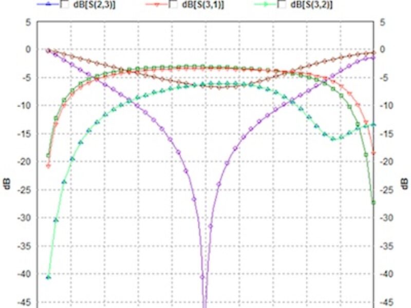
The simulation results were as expected with the unbalanced port 1 being matched and measuring a return loss of -53 dB in the center of the band. S21 and S31 are balanced and measure -3dB in the center of the band. The single ended return loss of S22 and S33 as well as the cross coupling parameters S23 and S32 measured -6 dB in the center of the band. These results are shown graphically in Figure 5.

Figure 5: Plot from IE3D shows the balun’s performance across the frequencies of interest
The phase balance also was as expected, as there is a 180-degree phase difference between paths Ang[ S(2,1)] and Ang[S(3,1)], illustrated in Figure 6.


Figure 6: The balun provides 180-degree phase balance
Next, the balun layout was then configured as a two-port device with port 2 and port 3 configured as a single differential port, as shown below in Figure 7.

Figure 7: The Marchand balun configured as a two-port device
The simulation results again were as expected with the unbalanced port 1 being matched and measuring a return loss (S11) of -53 dB in the center of the band. S21 the single to differential through path measures low loss in the center of the band. Figure 8 shows the differential port return loss (S22) measured -35dB in the center of the band.


Figure 8: Simulation plot for the two-port device
FastEM simulation leverages the IE3D ability to parametrically model a structure’s key performance critical geometries, and completely characterize the structure over a user-selected frequency range. This characterization data is kept in a FastEM database and enables users to do real-time EM tuning on the structure, and more importantly, allows the user to input a target electrical performance for the structure and then have IE3D automatically determine the best structure geometry and provide the desired s-parameter model for the structure. Using FastEM removes the guesswork of creating the best layout to meet the desired performance objectives.
After the tuning variables are defined, FastEM simulation can be run to get a series of simulation results. Then users can open FastEM Design Kit, as shown in Figure 9, to do real-time tuning, optimization etc.

Figure 9: FastEM simulation in IE3D allows users to perform real-time EM tuning using sliders to control the tuning variables. Click graphic for larger (PDF) version.
Figure 9 shows the parameterized Marchand balun structure and three separate tuning variables (sliders) defined as part of the FastEM simulation. The designer can perform real-time EM tuning by moving the sliders individually and see the geometry and the s-parameter model curve changing dynamically in relation to each slider. Real-time EM tuning helps the designer better comprehend the effect each parameter has on the structure performance, which can then be used to improve the original layout architecture.
Once the device architecture is finalized, the FastEM dataset can be shared with other designers thereby capturing the EM expertise of the device architect for reuse. Other designers can specify specific performance requirements via an optimization dialog and then determine the best layout and s-parameter model that meets the new performance objective. This is a good way to facilitate IP reuse of common passive design structures like inductors, baluns, filters, and transformers within the same company.
Conclusion
Baluns are very beneficial passive support circuitry used in high-frequency circuit design. The most frequently used application is connecting unbalanced or single ended circuits to balanced or differential circuits. In addition, IE3D’s FastEM capability allows designers to capture the EM design expertise of a device architect as part of an IP reuse strategy. FastEM changes the traditional layout-model-analyze-repeat design process to a correct by design paradigm. Users can quickly determine the best physical layout for a particular Marchand balun that may fit the HBT and pHEMT push-pull amplifiers, balanced mixers, or any of the numerous applications.
About The Authors
Mark Forbes is Content Manager for Mentor Graphics Corporation with more than 30 years in electronic design, antenna design, product marketing, and documentation. Mark has patents in antenna design and digital communications, and is inventor of the Ventenna, a concealed antenna system. He has a BSEE from Bradley University in Peoria, Illinois. mark_forbes@mentor.com
Mark Gorbett has over 20 years of experience designing complex RF/Microwave and analog circuits and currently owns and operates Microwave Assurance, LLC, an engineering consulting firm specializing in RF/Microwave, Analog, and EM design. Mark received his BSEE from Purdue University and also holds a Master of Science degree and Post Masters Certificate in Microwave Engineering and a Masters in Computer Science from Johns Hopkins University. gorbema@hotmail.com
References
- Zhen-Yu Zhang, Yong-Xin Guo, L.C. Ong, M.Y.W Chia, “A New Planar Marchand Balun, pp 1-5. wwwee.uta.edu/online/adavis/ee5349/wepi-1_balun.pdf.
- Rajesh Mongia, Inder Bahl, Prakash Bhartia, “RF and Microwave Coupled-Line Circuits”, pp. 391-435
- Chad Bliss, “Low Impedance Baluns For Push-Pull Power Amplifiers”, pp. 1-9.
- I.D. Robertson, S. Lucyszyn, “RFIC and MMIC Design and Technology”, pp. 155-161
 If you enjoyed this article, you will like the following ones: don't miss them by subscribing to :