Understand the science behind color mixing
High-brightness (HB) LEDs continue to increase in popularity due to the numerous advantages they offer when compared to the conventional lighting solutions. One of the advantages of HB LEDs is their ability to generate different colors, opening a new dimension to the world of decorative lighting.
Color mixing is essentially a process where a secondary color is generated by mixing the appropriate proportion of base primary colors. This article will explain the science behind color mixing, including the mathematical equations involved and how to implement them efficiently.
Science behind color mixing & multi-stimulus space
Primary colors are not a fundamental property of light but are often related to the psychophysical response of the eye to light. It is conceived that primary colors are completely independent from each other and sets of colors that can be combined to generate a useful range (gamut) of colors.
Similar to any other mathematical representations of physical phenomenon, color models can be expressed in different ways. Each has its advantages and drawbacks. The goal of modeling is to minimize formulation complexity and the number of variables while maximizing “substance” and breadth of coverage.
Historically, whatever the meaning assigned to the variables, three of them were enough to describe all colors: RGB, Hue-Saturation-Brightness (HSB), and other HS based models, such as L×a×b and xyY. One common feature was the number of variables or dimensions.
In multi-stimulus space, color stimuli are denoted by letters, such as Q, R, G, B, and A. Q represents an arbitrary color stimulus and the letters R, G, B, and A are reserved for fixed primary stimuli chosen for color matching experiments. The primary stimuli are Red, Green, Blue, and Amber.
A color matching between a given stimulus Q and the additive mixture in suitable amounts of the fixed various primary stimuli R, G, B, and A can be expressed by vector equation (Equation 1):
Q = RQR + GQG + BQB + . . . . + AQA
In multi-dimensional space, a color stimulus Q is represented by the multi-stimulus vector Q where the scalar multipliers RQ, GQ, BQ, AQ measured in terms of the assigned respective units of given primary stimuli R, G, B, and A respectively are called multi-stimulus values of Q.
The geometric representation in linear multi- dimensional space of Equation 1 is shown in Figure 1. The unit vectors R, G, B, and A represent the primary stimuli, defining the space. They have a common origin and point in four different directions.

Figure 1: Multi-dimensional color space
The vector Q has the same origin as R, G, B, and A. Its four components are located along the axes defined by R, G, B, and A, and have lengths respectively equal to RQ, GQ, BQ, and AQ, the multi-stimulus values of Q. The direction and length is obtained by simple vector equation defined by Equation 1. The space defined by R, G, B, and A is called multi-stimulus space. In this space, a color stimulus Q appears as a multi-stimulus vector (RQ, GQ, BQ, and AQ). In color mixing algorithm, the firmware calculates what these values should be to derive the color stimulus Q.
Color mixing
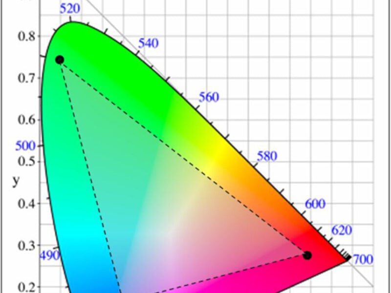
Figure 2 shows the CIE 1932 color chromaticity diagram. There are three LEDs, red, green, and blue, plotted in the figure. By mixing appropriate proportion of two primary colors such as red and blue, all colors along the line which joins red and blue can be generated, similarly when blue and green are mixed all the colors along the blue and green line can be generated.
Color mixing these three LEDs can generate any color that lies within this triangle. This area is called the color gamut. However, in the CIE 1931 standard, the color distribution is not homogeneous and contains discontinuities. Therefore, linear transformation cannot be applied to decide the proportion of primary color required to generate the desired secondary color.

Figure 2: CIE chromaticity diagram
Color-mixing algorithm
In color-mixing applications, the firmware inputs values in CIE chromaticity coordinate form. It converts the coordinates into appropriate dimming values for each LED channel. A dimming value is simply the percentage of maximum luminous flux to which an LED must be dimmed. If the current of an LED is quickly switched on and off in an intelligent fashion, the LED has its flux output controlled.
The firmware combines this coordinate with its preprogrammed knowledge of the characteristics of the LEDs in the system. It then completes the necessary transfer function that correctly converts the chromaticity coordinate into a dimming value for each LED. This process enables their light outputs to mix together to create the color of the chromaticity coordinate input into the system.
Multi-channel color mixing
In a three-channel color mix, if the color points of three LEDs are mapped onto the CIE 1931 chart, it forms a triangle. If the three LEDs are red, green, and blue then the triangle formed is called the color gamut (see Figure 2). The area inside the triangle is the gamut of achievable colors with this particular set of three LEDs. Any (x, y) coordinate within the triangle is input into the system. This provides a broad range and high resolution of unique colors that is produced with this system.
Four-channel color-mixing solution is based on the principle of superposition. It uses three-channel color-mixing algorithm as its base. For four-channel color mixing, if the color points of four LEDs are mapped onto a color space chart, it becomes apparent that there are exactly four triangles formed by the lines drawn between the four LED color point, Figure 3.

Figure 3: Superposition on four-channel color mixing
The method described here is easily expandable to more than four LED colors. In Figure 3, the four triangles are made up of the following LED triplets: TR1(R,G,B), TR2(R,A,B), TR3(R,G,A), and TR4(G,A,B).
Each triangle is solved for dimming values using three-channel color mixing functions. Out of these four triangles, two give all non-negative dimming values and two have one or all dimming values negative. Triangles with any or all negatives values are not valid and are discarded. Dimming arrays with all positive values are accumulated.
The interpretation of negative dimming values is that the desired point lies outside the triangle formed by three basic colors. For example, in Figure 4, RGB triangle returns all non negative values for P1; for P2, at least one dimming value is negative.
Two positive dimming values for each desired color are added and scaled appropriately. A negative dimming value implies that the desired color is not inside the gamut so that cannot be generated using the particular base colors.

Figure 4: Positive and negative dimming values
Color-mixing implementation details
The firmware uses CIE 1931 color space to input color requests. A particular point in the CIE 1931 color space is represented with three values (x, y, Y). The point is defined by (x, y) where x and y value represent the color hue and saturation. Hue is one of the dimensions of CIE 1931 color space. Saturation is the second dimension of this color space. The third value of (x, y, Y) vector specifies the luminous flux, in lumens (lm). The firmware must have inputs in the (x, y, Y) vector that specifies its color and flux output at some rated current and junction temperature.
Figure 5 shows the block diagram of a color-mixing algorithm built upon Cypress’ PowerPSoC family of controllers built around an 8-bit microcontroller and combining up to four independent channels of constant current drivers which feature hysteretic controllers. It also contains configurable digital and analog peripherals, operates from 7V to 32V, and drives up to 1A of current using internal MOSFET switches.

Figure 5: Block diagram for the implementation of
color-mix algorithm using Cypress’ PowerPSoC
The implementation of a four-channel color mix is based on a three-channel color mix. The first step in the algorithm is the creation of a matrix. Then, find the inverse of the matrix and multiply it with Ymix. Ymix is the number of lumens that the total mixed light output must produce. These steps are shown in Figure 6.

Figure 6: Flowchart for three-channel color mixing
The resultant Y values of the product are the lumen output of each respective LED that is necessary to create the requested color and flux.
At this point, all math operations give rise to two benefits of doing the math this way. If any of the final product’s Y values are negative, it signifies that the color coordinate that was requested is invalid. In other words, the requested color was outside the color gamut.
Also, check if any of the product’s Y values are larger than the maximum lumen output of any of the three LEDs. This means that the Ymix input was too large. In this case, the firmware scales back the values so that they produce the maximum possible flux at the requested (x, y) coordinate.
The flowchart in Figure 7 describes the steps required for four-channel color mixing algorithm. If the color points of four LEDs are mapped onto the chart, it forms four triangles. These triangles are made up of the following LED triplets: (R,G,B), (R,A,B), (R,G,A), and (G,A,B). These triangles are referred to as TRI1, TRI2, TRI3, and TRI4 in the flowchart.

Figure 7: Flowchart for four-channel color mixing
The three-channel algorithm is implemented to solve dimming values for each of these triangles. Each triangle is solved to calculate TRx. If any of the three dimming values obtained from this process are negative, then the solution is invalid. If the solution is valid, the three dimming values are saved. When two sets of three valid dimming values are obtained, there is no need to proceed with the other triangles.
The operation flow skips down to the “Add Two Sets of Dim Values” process as shown in Figure 7. The six saved dimming values are added together so that there are four values: one for each of the four LEDs in the system. These four values are scaled to the appropriate dimming resolution and the dimming value solution is complete.
Lastly, these four dimming values are given as inputs to the external or internal drivers which control the brightness of LEDs by modulating the current flowing through each channel. If any three of four solutions are invalid that means the desired color is not present in the color gamut.
The user can implement this error condition. It may be done by continuing to retain the old color, turning off the LED, and so on. These three-channel and four-channel color-mix algorithms can be extended to more LEDs, as well as to a variety of lighting applications.
About the Author
Anshul Gulati holds a Bachelors degree in Electrical and Electronics from BITS – Pilani, India. She has 8 years of experience in embedded systems design. Her interests include firmware development, digital design, and firmware/hardware co-design. She has worked on 8-bit, 16-bit and 32-bit controllers from different semiconductor companies likes Cypress, Motorola, Microchip and STMicroelectronics. She is currently working in CSBU R&D team developing solutions based on Cypress’ PSoC products, and can be reached at gula@cypress.com.
 If you enjoyed this article, you will like the following ones: don't miss them by subscribing to :