Configurable mixed-signal ICs and asynchronous state machines can optimize embedded designs
Abstract – There are always external components surrounding an embedded System on a Chip. This paper describes a new category of semiconductors based on advanced circuit design and non-volatile memory, Configurable Mixed-signal ICs, (CMICs). CMIC offer a better way to implement the unavoidable standard analog, logic and discretes. In many cases, embedded microcontrollers can be replaced with much lower power and more secure CMIC Asynchronous State Machines.
Keywords: Configurable Mixed-signal IC, Asynchronous State Machine, System on a Chip, CMIC, ASM, SoC, MCU
I. Introduction
Systems on a Chip for embedded devices offer an astounding level of integration. Advanced processes give SoC and MCU developers plenty of transistors to work with. These devices can integrate multi-core processors, wireless connectivity, memory as well as graphics controllers.
However, even the most sophisticated and highly integrated SoC or MCU requires some external circuitry for power management, human interface or connecting to sensors. As a result, there are almost always comparators, op amps, level shifters, various logic and discrete transistors scattered across a design. These SoCs are almost never truly systems on a chip.
In some cases, the support logic needed can be swept up into a low-end FPGA. But usually this is a expensive addition to a bill of materials and is not a cost saving over discrete components. It is also an inadequate solution since an FPGA cannot address the entire external circuit, namely the analog or discrete components.
For an embedded device, this challenge will be even more pronounced as an MCU or SoC cannot address all the possible sensor, power, and connectivity options. This is further complicated by the fact that any one embedded device will be much lower- volume than an SoC for a mobile phone application. Therefore, a typical MCU or SoC vendor will not be justified in spending the large sums needed to design and fabricate a device to support all the necessary permutations and integrate the required surrounding support circuitry.
So, are designers forced to put up with sub-optimal designs with stray logic, overpriced analog and space-consuming discretes? Will the next generation of embedded devices surrender valuable space (which takes away from more valuable battery volume) and be burdened by a bloated bill of materials?
Next: CMICs
II. Configurable Mixed-signal ICs
The answer is happily “No”, thanks to the emergence of Configurable Mixed-Signal ICs (CMICs). These devices are a clever matrix of analog and digital circuit functions that are configurable through One- Time-Programmable (OTP) Non-Volatile Memory.
The pioneer and leader of this new category of devices is Silego Technology. Although the concept of analog and digital FPGAs has been around a long time, Silego was the first company to truly think through the architecture, analog design and software issues. Silego introduced CMICs in 2009. Since then, Silego has completed over 1,300 customer designs and shipped over 2 billion configurable devices.
Silego’s CMICs offer a variety of analog and digital resources that a designer can configure into mixed- signal circuits. Included are:
Asynchronous State Machines
Timing Delays Counters
Pulse Width Modulators
Comparators
Voltage Monitors
Voltage References
ADCs
Glue Logic
Level Shifters
Designers can drag and drop these resources and “wire up” their design in a schematic capture tool, or they can emulate the design with the Silego hardware development kit. When they are satisfied with the design, they can program the CMIC device with the on-board OTP memory. CMICs can be used for a variety of essential mixed- signal functions. Some of the most popular are:
Motor & Fan Control
System Reset
LED Control
Over Voltage Protection
Power Sequencing
Voltage Detection
Frequency Detection
Sensor Interface
Port Detection
Temperature Control
These can be found in a wide variety of applications and markets and they are ideal for Embedded Designs.
Next: Advantages
III. CMIC Advantages
Configurable Mixed-signal ICs offer embedded designers and manufacturers multiple advantages over traditional discretes and analog:
Optimized Board Space
Convenient, Faster Way to Innovate & Prototype
Lower-Cost Bill of Materials
Confidential Design That Is Hard to Copy
Less Complex and Less Stressful Supply Chain
A. Embedded designs need optimized board space
A dozen or more components can take up precious real estate in any system. Today’s smartwatches and fitness bands can’t spare any board space. This space could be better used for a larger battery or a slimmer form factor.
A configurable mixed-signal IC can integrate several components into one tiny product. Depending on the functions supported, these range in size from 8-pin 1.0mm by 1.2mm to 20-pin 2.0mm by 3.0mm STQFN packages.
Board savings will depend most importantly on the type and number of functions implemented. Customers have seen space reductions of 60-90% by integrating 12-30 components or more. For this reason, designers of embedded devices are especially enthusiastic users of Configurable Mixed-signal ICs.
B. Embedded designs need a more convenient, faster way to innovate and prototype
Traditional circuit prototyping involves multiple time consuming steps:
Circuit design
Part selection
Ordering samples and then waiting for the parts to arrive
Laying out a board, hand assembly of sometimes dozens of parts
Debug
And repeat…..
This process can take many days if not weeks. Engineers don’t want to wait for parts to arrive or spend time doing tedious assembly. They want to get to work and get results quickly.
Prototyping with configurable mixed-signal IC is much faster. Schematic capture, emulation and programming can be done in the same day. CMICs are very like FPGAs but with analog functionality. The CMIC process makes “what if” exploration easy as well. Changing a function is as easy as making the schematic change and programming a new part.
C. Embedded designs need lower-cost bill of materials
It is easy to see how a configurable mixed-signal IC allows for an easier design process and faster development. It is also easy to see how valuable board space can be saved by using CMICs. However, unlike traditional FPGAs, Configurable Mixed-Signal ICs don’t offer these benefits at a price premium. CMICs have been designed to reduce the bill of materials cost over discrete and analog components in most situations. A recent design profiled on embedded.com highlighted that 1 CMIC part replaced $1.50 of level shift and comparator circuitry with a single $0.35 CMIC. This CMIC delivered significant savings with an opportunity to include even more functionality with its unused resources. There are several reasons for the relative cost effectiveness of CMICs:
• The One Time Programmable NVM is very cost efficient. CMICs are designed and fabricated in a single process node that is a sweet spot for die size, analog performance, digital density and cost per layer and assembled in a single packaging technology.
• Analog components and discretes are priced relatively high on a per-function basis.
• The suppliers of analog and discrete components are not motivated to reduce or improve their low ASP product cost structure. For many of them it would require going fabless or redesigning.
D. Embedded developers want a confidential design that Is hard to copy
A discrete circuit with standard off the shelf components is easy to copy or clone. A CMIC design is unique to the customer who designed it. This makes it very difficult to copy or reverse engineer. This helps designers of consumer products maintain a competitive advantage where there might be dozens of would-be competitors looking to knock off their innovative designs. The CMIC circuitry inside is as secure as a full custom IC and only the designer or its designated ODM and supply chain partners can procure it.
E. Embedded manufacturers require a less complex and less stressful supply chain
An important effect of avoiding or integrating multiple components is reduced complexity for a supply chain. Fewer parts to qualify, fewer to order, fewer to inventory; these factors have positive bottom line impacts. By reducing multiple parts, the risk of being in allocation or not being able to get a particular component device is reduced. It only takes a single discrete transistor to go on allocation or end of life to bring a line down or cause other serious issues.
Next: No static power
IV. No static power and no-code asynchronous state machine versus low power MCU for embedded applications
When designing portable systems, size and battery life constraints are often the most severe challenges to overcome. One traditional way to pack a lot of functionality into a small size and power budget is to use a low power microcontroller such as TI’s popular MSP430. These types of ultra-low power microcontrollers offer high levels of flexibility and are available in small packages, allowing a system to run for not only days, but months and years on a single battery cell.
Silego Technology has taken a different approach in attacking this same problem, by adding a user programmable asynchronous state machine (ASM) macrocell to our fifth generation GreenPAK (CMIC) product family. The following comparisons illustrate design tradeoffs and tips that the user may consider when choosing between a variety of microcontroller options, and doing the same job using an ASM like the one in inside a CMIC.
A. Handling MCU code
CMIC’s ASM contains 8 states and 24 possible decisions.
• STATE(X): If Signal One is high, then go to STATE(A). This is a decision statement to determine the next state; each state can be the resultant state only three times.
• State A is a configuration that causes an output to blink an LED. This is the actual result. To move to the next state (result), another decision must be made.
• STATE(A): o If Signal Two is high, then go to STATE(B)
o If Signal Three is high, then go to STATE(D)
o If Signal Four is high, then go to STATE(F)
• STATE(B) might cause an LED to blink faster
• STATE(D) might wait 500ms before moving on to another STATE.
• STATE(F) might check the POR or a power good signal.
So the ASM in CMIC represents an MCU program with up to 24 IF..THEN statements. When the 8 state ASM capabilities are considered together with hardware input and output circuits, the CMIC may be represented as being roughly equivalent to about 100 lines of standard C code written for common 8 and 16 bit MCUs.
As the name implies ASMs have no clock. A CMIC ASM is event driven and does not operate with a clock. As such, when there are no events, the ASM stays in one state and consumes no static power. Thus, applications with limited input cycles can operate at leakage current power consumption well in to the single digit nanoamps of average current consumption at room temperature. Applications such as resets, power sequencing, various sensor interfaces, long-term data logging may benefit from a real ASM.
B. Handing embedded control problems
Typical embedded control problems usually involve a system that is transitioning through a set of discrete states based on asynchronous external inputs. ASMs are the natural problem solver for most embedded control problems. However, most designers opted for traditional microcontrollers resulting in asynchronous state machines being pushed to the edges of engineering. However, due to inherent power and speed advantages of ASMs the on-going low-power portable consumer/embedded/IoT revolution has renewed interest in ASMs.
Silego has revived and modernized the ASM, mitigating the well-known hazard and race conditions, the programming/configuration headaches, while retaining all the inherent low- power, low-latency benefits for simple (up to 8 states) embedded control problems that would require less than 100 lines of code.
The types of embedded control problems that can be solved by a CMIC ASM are limited by:
a. The number of inputs: 18
b. The combinatorial logic blocks processing the 18 inputs: 17
c. The number of total states: 8
d. The number of decisions: 24
e. Resolving basic true/false decisions from combinatorial logic
f. Is the voltage higher or lower than X volts?
g. Is SignalA XOR SignalB = 0 or 1?
h. Has timer Z finished?
i. 4 analog comparators
j. 1.8 to 5.5V VDD
k. ~25MHz digital signals
Silego’s CMIC has almost no computational power and is therefore not good for digital filtering, solving multi-bit math problems, graphics, vector calculations, etc. Silego’s CMIC has only 8 bytes of I2C addressable memory and is in most cases not suitable for an interface converter.
An intelligent flashlight is an easy to understand example of how the CMIC ASM could be used. This flashlight has an OFF state, a High Brightness State, a Low Brightness Battery saving State, A flashing State, a Battery Status State. The CMIC ASM can easily be set up to cycle between these states perhaps with button pushes or multiple button inputs. The output drive MOSFET can be control by the CMIC to achieve high steady current through the White LED or lower current or flashing current depending on the configuration of the combinatorial logic as activated by the ASM’s 8 output bits.
IO port expansion is another easy to understand application example where CMIC can be found useful. CMIC comes with an I2C port that can be used to directly drive outputs, the ASM, or combinatorial logic. As mentioned the I2C could write directly to a pin, however, the ASM can also be used to be configured such a bit from the I2C bus can move an ASM state which in turn outputs a parallel 8-bit pattern. Each state can have its own parallel 8-bit output. Even a single pin transition periodically between high and low can be used to move the ASM between states and thus cause up to 8 pins to have a state dependent pre-configured output.
Next: Overkill
C. Overkill microcontrollers versus CMIC ASM value
Microcontrollers contain a processor, program code, stack memory, and various peripherals. Microcontrollers can easily perform the application examples above but are inefficient in size and power. In is quite common to find MCUs designed into applications where less than 1% of the MCU horsepower will ever be used.
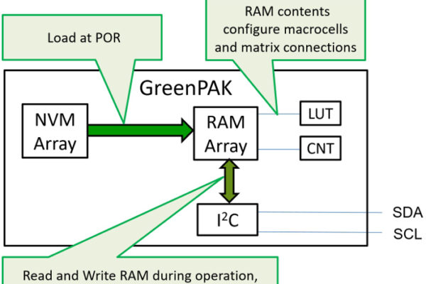
A device such as CMIC’s ASM is well suited to simple embedded control applications, especially ultra-lower power applications (see Figure 1). In fact, most MCUs are computational power and cost overkill for these simple embedded control applications making a CMIC ASM, a no code, no static power, ultra-small-size, easy-to-use option.

Figure 1. GreenPAK with ASM
D. Interrupt latency (nanoseconds versus microseconds)
When doing state machine design on a microcontroller, this is done in software running on the microcontroller core. In this case, the states are implemented as points in the software instruction execution, and state transitions are implemented with conditional software branching. Microcontrollers have the capability to also process asynchronous inputs, and they do this through dedicated interrupt controller hardware, and through interrupt service routines (ISRs). The ISR is software that is run after a hardware interrupt has been activated.
An important benchmark for microcontrollers is how short is the time from an external interrupt signal until the core is executing the first instruction of the ISR, the so-called interrupt latency. MCU interrupt latency in general purpose devices is usually measured in fast examples at around 5 to 10 microseconds.
An ASM equivalent of interrupt latency is measured in nanoseconds – equivalent to the unclocked time of flight through the few gates between an external pin and the internal ASM input. The ASM has latency from one state to the next. If the CMIC is operating at 5V power supply, the latency is a maximum of 50ns. Yes, ASMs are extremely fast and extremely low power. Even worse, MCU interrupt latency includes a variety of tasks that the microcontroller must do before it can execute this first instruction, including latching the external signal, finishing execution on the instruction currently in progress and saving state (pushing registers) to be able to return to the same state.
Depending on the microcontroller, the latency measured in cycles can be as small as 10 to 20 cycles. Multiplying these cycles by the clock speed yields the interrupt latency. There is also an impact from running a high-level language (such as C), as this usually increases the number of cycles for the interrupt latency. Similarly, if the user is running an operating system, this can also add extra cycles to the interrupt latency.
There is a trade-off that the microcontroller user must make if power and fast interrupt response are both required in the system, as the faster the clock speed is set, the lower the interrupt latency will be, but a faster clock speed will also drive up the power consumption. Some microcontrollers allow the system clock speed to change over time, so that the system clock speed can be set low when the system is waiting on an asynchronous input, and increased when the interrupt is requested. This can be a method to save power and decrease interrupt latency, but there is a limit to how useful this is, as there is also latency in changing the clock speed. No such tradeoff is necessary with an ASM.
E. VDD variation
A CMIC ASM works over a wide voltage range. A properly designed ASM is guaranteed hazard and race condition free because each ASM signal path is guaranteed by signal length and gate count. Thus, as the VDD changes, so does the propagation delay. However, the propagation delays are all matched and thus performance is guaranteed.
Microcontrollers, on the other hand, are clocked with signals that are not correlated well with VDD. As the VDD changes, the MCU propagation delays change and since the timing doesn’t change, the timing margins are soon compromised. Chip designs react to these design hazards but putting the MCU under a voltage regulator or requiring still more performance to be lost by slowing the clock speed. However, the voltage regulator consumes power, and the slower clock speed increases interrupt latency.
Next: Crash, no crash
F. Crash versus no crash
Design and system flaws that can cause a microcontroller to crash. Poorly written software, timing issues, miscalculations of interrupt latency, running out of stack memory, memory leakages, and accidental writes in program memory are some common pitfalls that cause MCUs to crash.
Silego’s ASM is configured in hardware with NVM bits, has no timing issues, latency measured in nanoseconds, no stack memory, no ability for memory leakage, and no ability to unintentionally overwrite program memory, and is therefore inherently more robust with VDD noise and brownouts.
It is common to find Silego’s GPAK ICs and CMIC’s ASM being used as crash monitors for large MCUs, SOCs, and ASICs. Some are also used to operate the failure mode notifications, error LEDs, and other functions that must remain operational while the main processor is malfunctioning.
G. No-code GUI-based tools versus typical MCU tools
A CMIC ASM is configured using the GreenPAK Designer development environment. The software appears to be a schematic capture editor instead of a coding tool. Most state machine designs can be implemented in a matter of minutes reducing the typical MCU tool learning curve from months to Silego’s GPAK learning curve of a few days.
Inside this tool, a special bubble state diagram tools allows the designer to select and name the various states in the system, point and click to add state transition arrows in the same manner that an engineer would draw a state diagram on a white board.
After configuring the state machine the designer returns to the schematic capture editor to graphically connect the hardware signals to each of the state transition decision points. It is common for a design engineer to be able to complete their first prototype in one day of effort.
H. CMIC size versus low-power MCUs
Without all the complexity of the MCU architecture the CMIC is usually smaller, especially when compared to 1.8 to 5V tolerant, low-pin count, ultra- low power MCUs. If a CMIC product can perform the control function, then it is also usually the smallest programmable option on the market at 2 x 3 mm 20-pin STQFN. For applications that require less control; other CMICs are offered in packages as small as 1.6 x 1.6 mm 12-pin STQFN.
Next: Final point
V. CMICs make embedded design easier and products better
In summary, the tiny CMIC with the 8 state ASM can take on a variety of embedded control applications that would formerly have been the exclusive domain of microcontrollers. The easily configured ASM brings key advantages of ultra-fast state transitions, leakage level static current consumption, robust design, and supply voltage tolerance so important in IoT, portable, mobile and embedded applications.
In addition, CMICs offer many benefits that will make embedded designers’ work easier and their products more profitable. They are the ideal solution because board space is tight and needs to be maximized to save space for other valuable functions (such as a bigger battery). They also make procurement happy by saving significantly over traditional analog and discrete while dramatically reducing the risk and stress involved.
Acknowledgment
Thanks to John McDonald and Nathan John of Silego for their “ASM versus MCU” article which was used as the basis of the ASM section of this paper.
Related links and articles:
News articles:
Startup launches configurable power management ICs
Silego: Voltmeter and Ammeter Autorange Control
Silego: Voice-activated smart home controller
Silego: Introduction to stepper motor control
 If you enjoyed this article, you will like the following ones: don't miss them by subscribing to :